Why this camera?!#
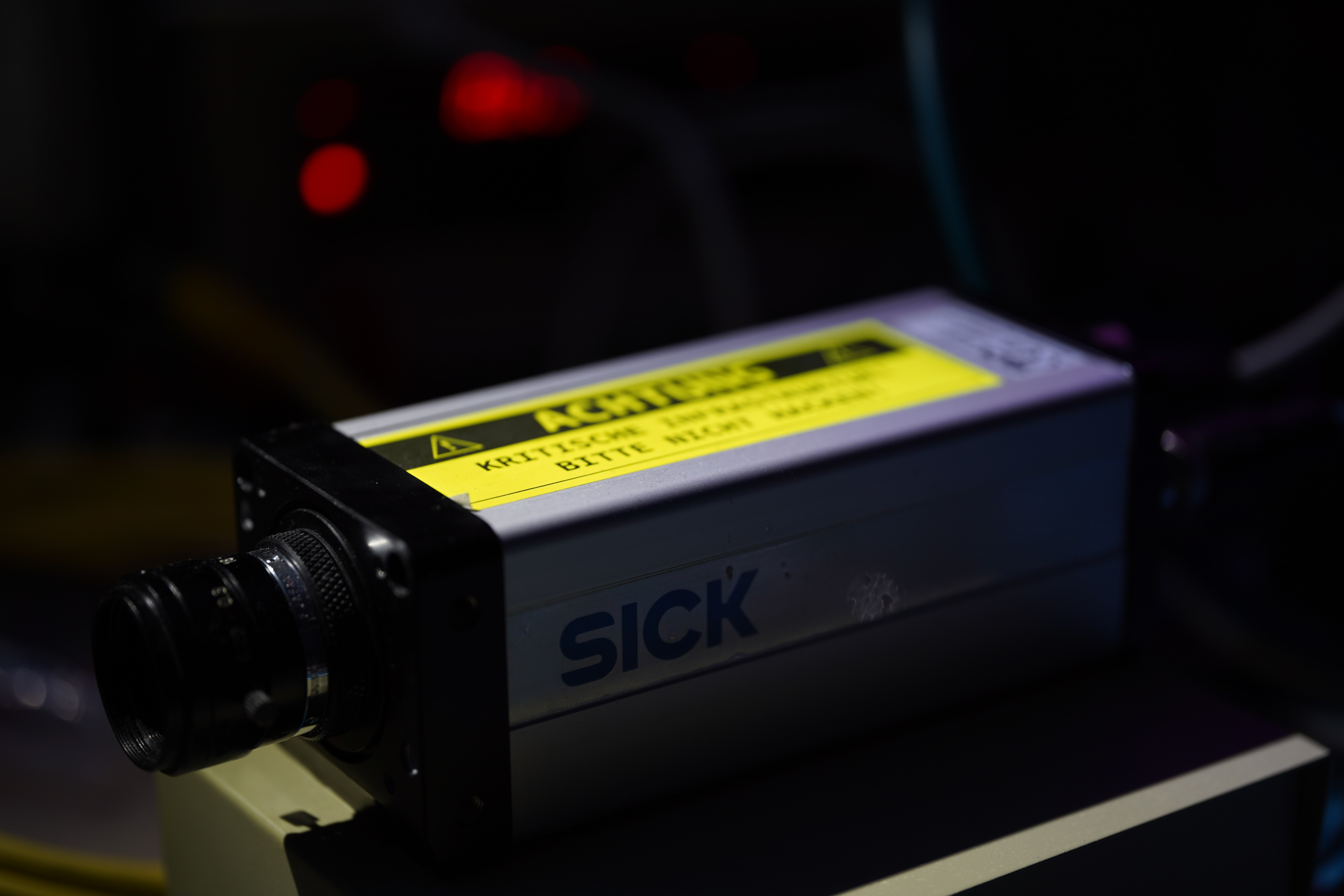
I bought a SICK IVC-2DR1111 together with a Fujinon HF16HA-1B on eBay for \(46.69\,€\). That is really cheap considering, that the exact same model was sold twice after that for more than ten times my price (maybe I should sell this thing…). Just the lens alone is worth triple of what I have paid for the complete kit.
When buying this camera in March 2025 I was oblivious to the amount of complexity hidden in this device. I simply wanted to play around with a global shutter industrial camera that has an ethernet port for easy IO (lol, foreshadowing). So I searched for the cheapest industrial camera I could find on eBay … what could go wrong? The camera supports a full suite of image processing and analysis tools on board. These tools can be used by the user through programming a routine via SICKs IVC-Studio, which is a Software, that lets you program via GUI blocks. The software is old and clunky and also windows only. I do not want to have to use this for day to day operation of this device though.
Interestingly enough, I could probably trace this camera’s origins because the program on the device contained steps for supervising and documenting a cable crimping process, as well as a routine for uploading the crimp images to an FTP server with a local IP address and stored credentials.
However for now I only want to get images out of the camera and send to a PC via network so I can use them in Python or similar for whatever I want. IVC-Studio offers to program some IO operations onto the camera. The only option to receive image data via these interfaces would be the FTP upload. However that would need to always be triggered before by some other operation in the program. So no simple live image stream.
Supplying power and network#
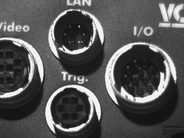
But before starting to reverse engineer a way to get image data without bothering to program the camera, I need a way to power it. The cameras manual luckily allows me to assemble an 8-pin M12 Connector, that I purchased from AliExpress. I only populated pin 7 (GND) and pin 2 (DC 24V). The network cable is also M12 (but 4-pin). I had a SICK network M12 cable ling around from some other device. Therefore i could just use that directly.
Hooking it up to my bench PSU, it sure powers up and the lights on the back light up.
Getting the camera to connect to the software was less of a pain than i expected, as I simply needed to use Wireshark to sniff on that interface to see if the camera is trying to establish a connection and then mimic the expected connection settings. I then switched the camera to DHCP operation for experimenting.
First observations#
The camera provides three image banks that can hold images for storage as well as for image operations while powered on. These image banks can be viewed live in IVC Studio. That means they must be transmitted somehow over the network. So I started Wireshark on the old Microsoft Surface I use for IVC Studio, as it’s my only Windows PC. I then triggered the capture cycle of new images in three scenarios via a small GUI program I ‘wrote’ in IVC Studio: with a lens cap on (black), with a light source pointed directly into the lens (white), and one that was almost properly focused, hoping this would make it easier to spot the images in the network traffic. What I didn’t realize at first was that I was only capturing the thumbnail versions of the images, which are smaller than the sensors \(640\times 480\) resolution. I’ll get to how I noticed this later — the format itself doesn’t actually change.
Wireshark#
Finding the images in the output of Wireshark surprisingly wasn’t too hard, as the packets were all the same size (except for the last) and much larger than the rest of the traffic.
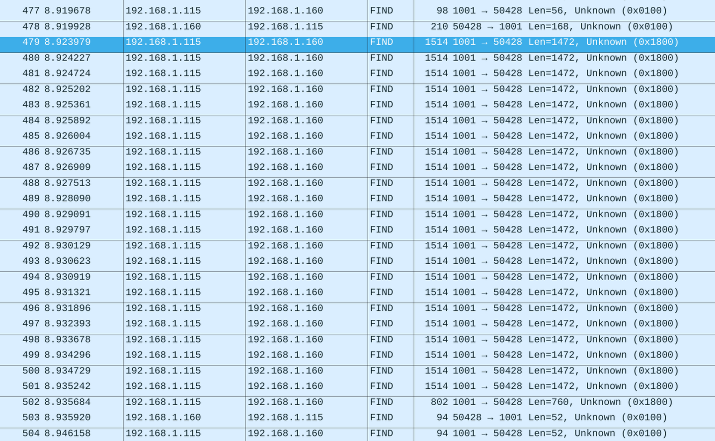
The traffic appeared as UDP packets (they show up as “FIND” for whatever reason, but they’re not). All values in the header seem to be little-endian. I figured this out by trying both big- and little-endian on different chunks of the header until I found the known horizontal and vertical sensor resolution, which gave me confidence that the endianness was correct. One image frame is split across several packets (see image above). The first packet contains an extended header with metadata (frame dimensions, total size, etc.) as well as the first chunk of image data. The subsequent packets contain a shorter header and additional raw image data. I realized the data was raw because there was no sign of 0xff 0xd8, which would indicate a JPEG segment. Also, the number of data bytes matched the resolution exactly.
This is what the first packet looks like for the white image. The following is only the UDP part of the message. The bulk of the content is a repeated ‘0xf2’, which is the image data, as the black image is identical but contains bytes close to 0 on these locations instead:
0000   18 00 00 00 00 00 00 00 c0 05 00 00 b8 85 00 00
0010   18 00 00 00 00 30 00 00 00 00 0f 00 ff ff ff ff
0020   00 00 00 00 a0 85 00 00 00 00 00 00 00 00 00 00
0030   d5 00 00 00 a0 00 00 00 00 00 00 00 80 02 00 00
0040   e0 01 00 00 00 00 00 00 01 00 00 00 00 00 00 00
0050   01 00 00 00 00 00 00 00 01 00 00 00 00 00 00 00
0060   00 00 00 00 00 00 00 00 00 00 00 00 00 00 00 00
0070   00 00 00 00 00 00 00 00 10 27 00 00 20 4e 00 00
0080   00 00 00 00 00 00 00 00 00 00 00 00 00 00 00 00
0090   00 00 00 00 00 00 00 00 00 00 00 00 00 00 00 00
00a0   00 00 00 00 00 00 00 00 f2 f2 f2 f2 f2 f2 f2 f2
00b0   f2 f2 f2 f2 f2 f2 f2 f2 f2 f2 f2 f2 f2 f2 f2 f2
...
05b0   f2 f2 f2 f2 f2 f2 f2 f2 f2 f2 f2 f2 f2 f2 f2 f2
Comparing that to the header of all subsequent UDP payloads shows, that there is clearly more info in the first one.
0000   18 00 00 00 01 00 00 00 c0 05 00 00 b8 85 00 00
0010   f2 f2 f2 f2 f2 f2 f2 f2 f2 f2 f2 f2 f2 f2 f2 f2
...
05b0   f2 f2 f2 f2 f2 f2 f2 f2 f2 f2 f2 f2 f2 f2 f2 f2
From what I can observe, the first byte is 0x18 for transmission of thumbnails and 0xd4 for full sized images. After that, there is a packet counter for the packets of the current frame. The header alo contains package length in little endian (0xc0 0x05) and another part, which is not identified at this point.
Decoding in Python#
As I wanted to understand the way this device speaks before writing any clean code, i made some super crude python scripts that read the .pcap files from Wireshark.
Image packet header#
This part is about the first 16 bytes, that are shared between all image packets.
print("Total len", len(data))
print("Identifier", int.from_bytes(data[:4], 'little'))
print("Packet Counter", int.from_bytes(data[4:8], 'little'))
print("Length", int.from_bytes(data[8:12], 'little'))
print("???", int.from_bytes(data[12:16], 'little'))
print("Data len", len(data[16:]))
This highly complex piece of software technology prints out the following, when fed with a packet of a thumbnail image:
Total len 1472
Identifier 24
Packet Counter 1
Length 1472
??? 5277707
Data len 1456
The total length of the UDP part matches a 4 byte value in the header, that seems promising. We identified the packet counter earlier. So apart from that large value I have cracked this part.
Image header#
This header is different as it does not happen on every packet, but on every image. I took the same approach to decode this by writing this high-tech software to decode the image header.
print("???", int.from_bytes(data[16:20], "little"))
print("???", int.from_bytes(data[20:24], "little"))
print("???", int.from_bytes(data[24:28], "little"))
print("???", int.from_bytes(data[28:32], "little"))
#print("Zeros?", int.from_bytes(data[32:36], "little"))
print("???", int.from_bytes(data[36:40], "little"))
#print("Zeros?", int.from_bytes(data[40:48], "little"))
print("Data Width", int.from_bytes(data[48:52], "little"))
print("Data Height", int.from_bytes(data[52:56], "little"))
#print("Zeros?", int.from_bytes(data[56:60], "little"))
print("Sensor Width", int.from_bytes(data[60:64], "little"))
print("Sensor Height", int.from_bytes(data[64:72], "little"))
print("???", int.from_bytes(data[72:80], "little"))
print("???", int.from_bytes(data[80:88], "little"))
print("???", int.from_bytes(data[88:96], "little"))
#print("Zeros", int.from_bytes(data[96:120], "little"))
print("???", int.from_bytes(data[120:124], "little"))
print("???", int.from_bytes(data[124:128], "little"))
#print("Zeros?", int.from_bytes(data[128:168], "little"))

# Everything else seems to be data
This will produce the following:
??? 24
??? 12288
??? 983040 # I will later figure out, what this and the following 4 bytes are doing...
??? 4294967295
??? 34208 # This turned out to be the number of remaining bytes directly after this value (without counting the 16 packet headers)
Data Width 213
Data Height 160
Sensor 640
Sensor 480
??? 1
??? 1
??? 1
??? 10000
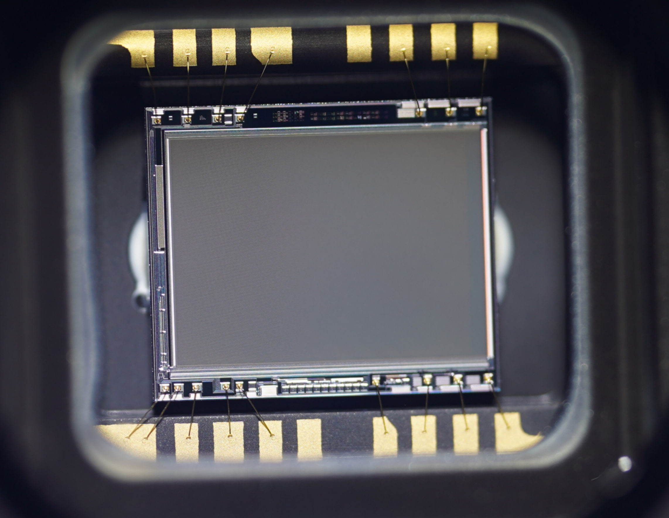
??? 20000So this begins with some unknown values, followed by a total size in bytes and the resolution of the sensor as well as the thumbnails resolution. In case of a full image the Data width and Data height are \(640\times 480\) as well. Now that we have the correct width and height for the final image, we can dump the data from the packets into an image using Python. Filling the image array line by line with the collected data from the .pcap file produces the following result.
YAY! 🦀
But i think there is more to reverse on this camera…for example how to trigger the transmission of such an image without the need of IVC-Studio.