Checking out the lamp#
I have a cheap UV lamp that I want to use to cure UV-resin for PCB repairs.
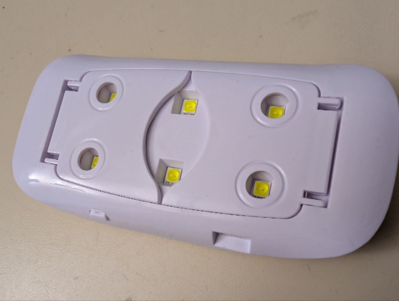
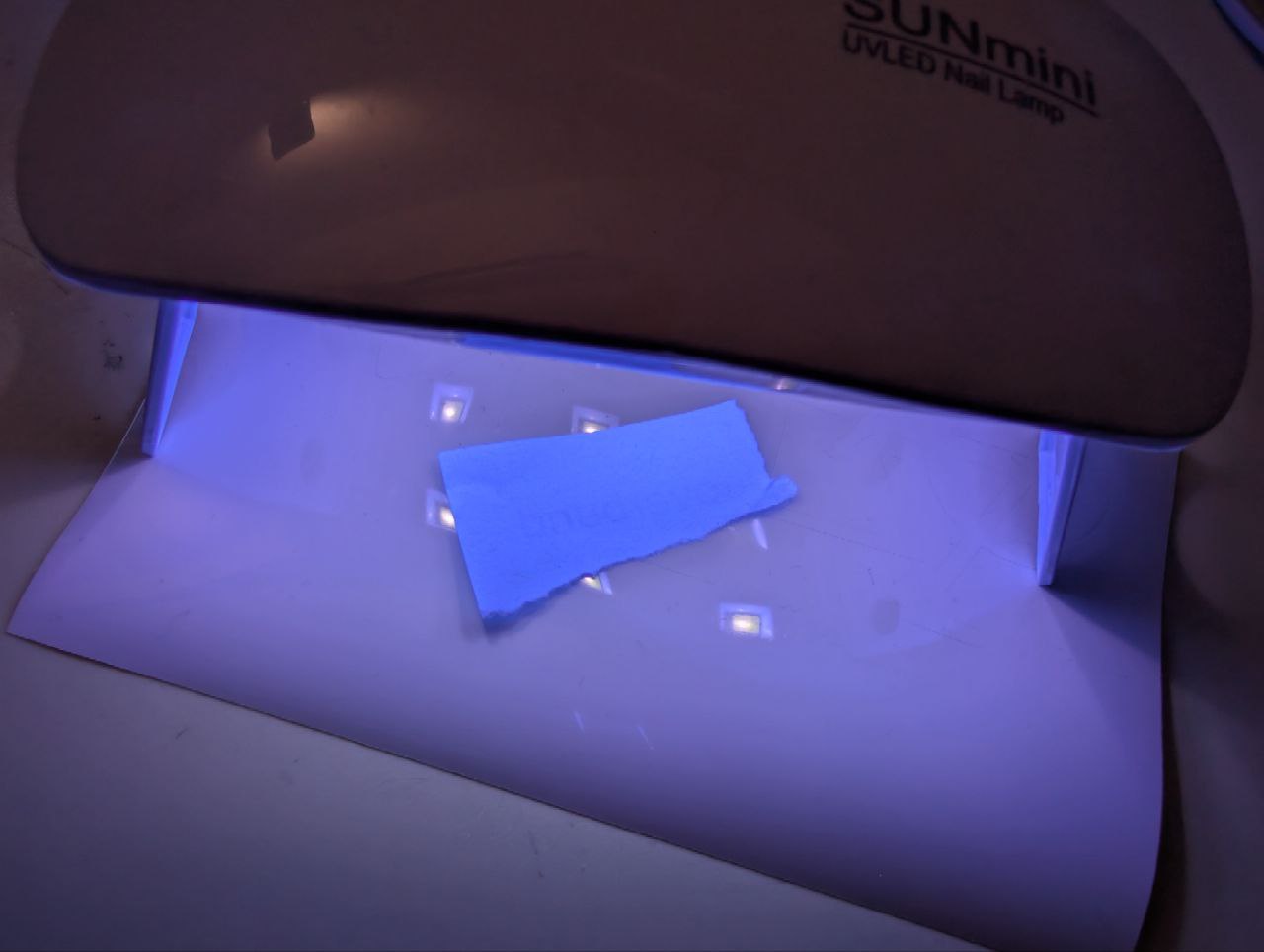
While the lamp was very cheap, it does indeed output UV light, as the resin cures. The lamp has a large issue however. It gets hot! This would not be a huge problem, if it would not turn off roughly \(20\,s\) after pressing the power button.
The reason why I believe this shutdown feature was incorporated is the high heat generation and the costs that would be associated with a reasonable thermal design. The PCB is of the aluminium backed type, but that is not enough to carry away a lot of heat, as I will see in the thermal camera image.
Getting temperature under control#
Lets measure how warm this device gets after one operational cycle.

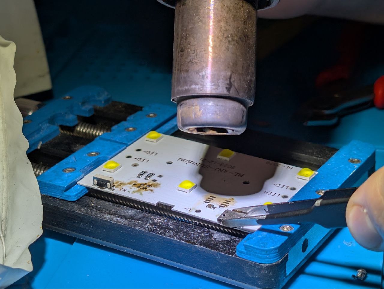
I looked into my box of heat sinks and found one that has an area larger than that of a cpu dye from a low power PC that will fit the PCB of the lamp perfectly. It also has an active cooler so for very long runs, this might help.
For testing I ‘mounted’ the PCB to the cooler with a simple clamp
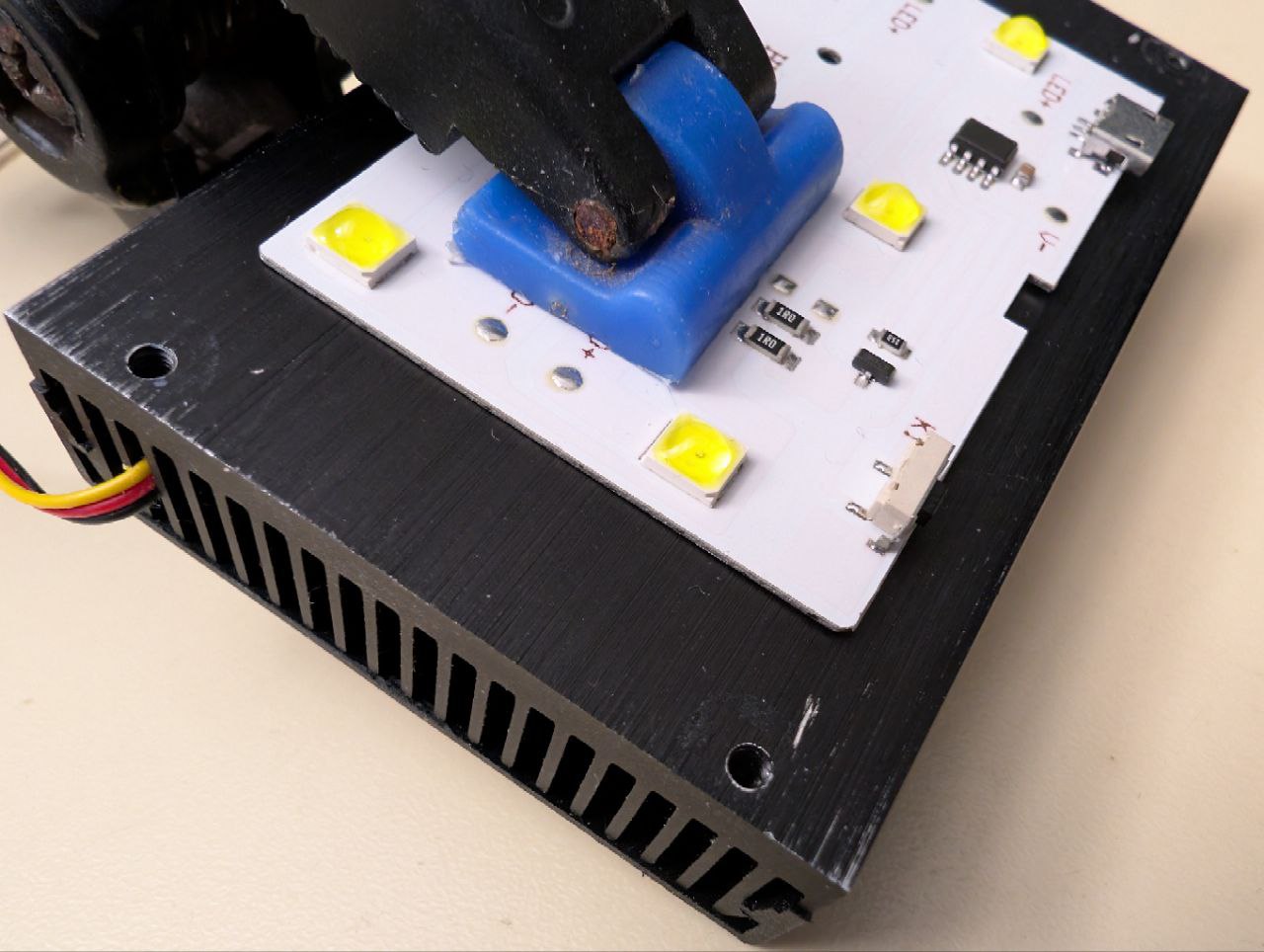
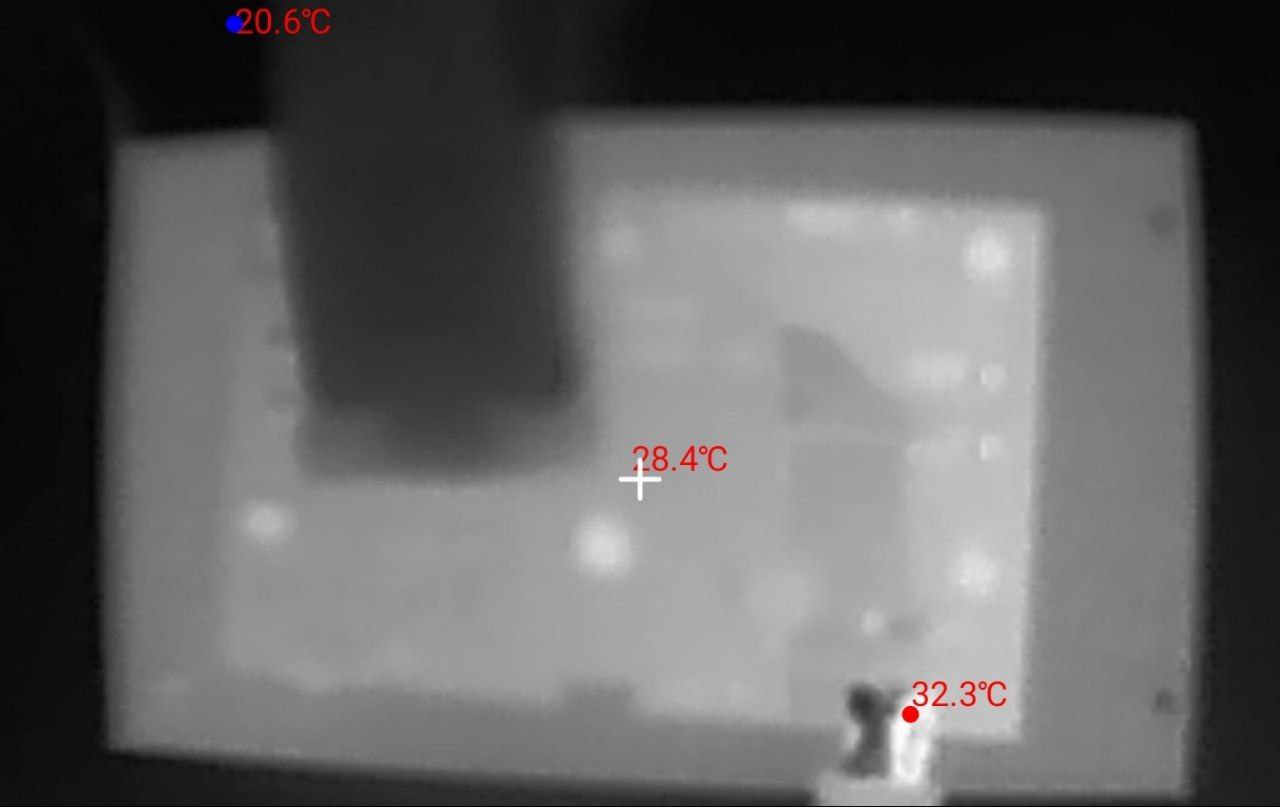
Well the results speak by themselves! The LEDs are not even registered as the hottest part anymore. The hottest point is now only \(32.3^\circ C\) and likely a reflection of my hand on the metal of the USB port. This is HUGE! The temperature delta is more than \(20.0^\circ C\)!
Understanding and modding the circuit#
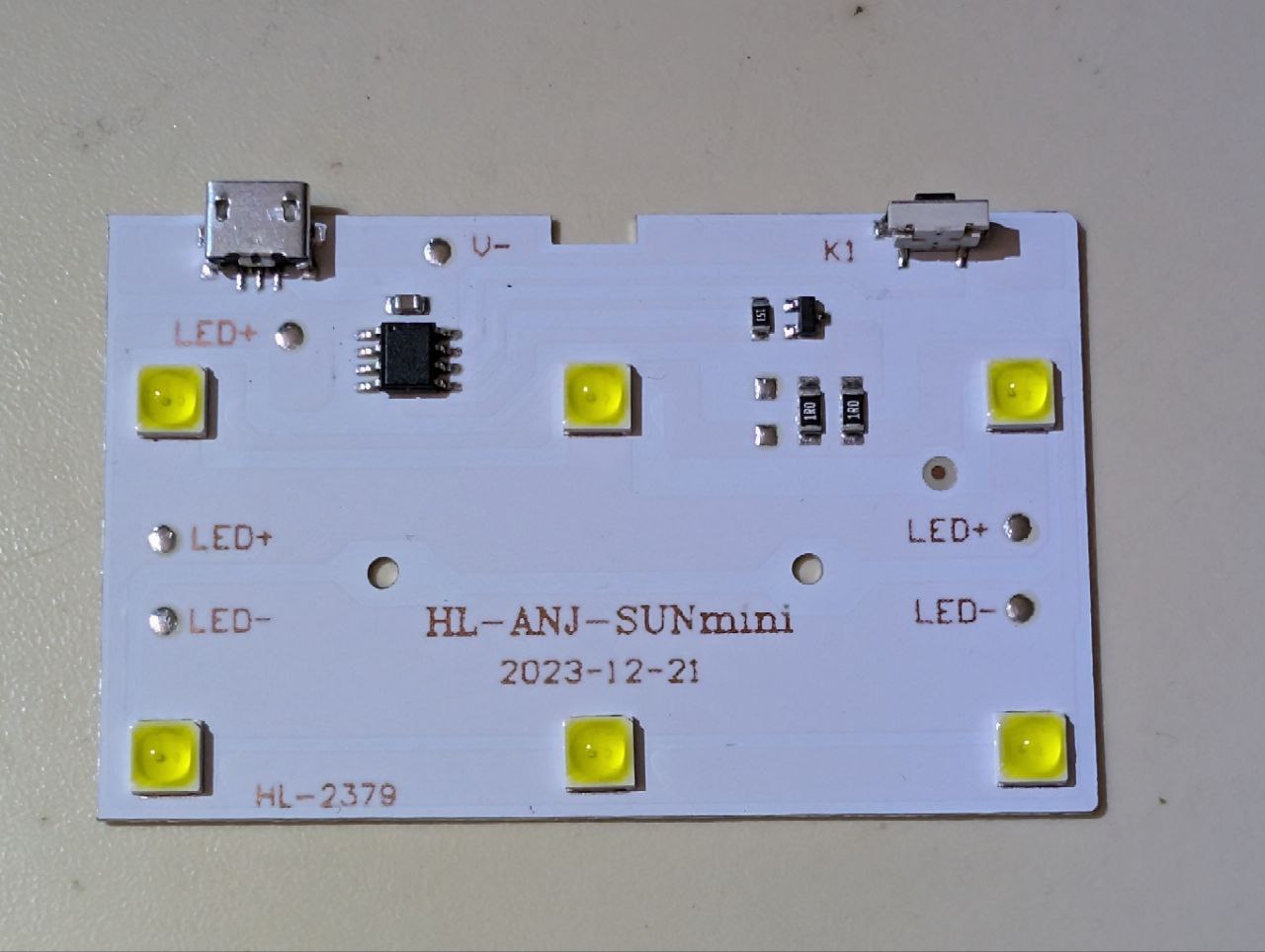
Ok, now that I can say the temperature problem is ‘solved’, lets look at the electronics

SW1, IC1 and Q1 are part of the timer. IC1 is not identifiable as it has no markings.Luckily, the schematic is very simple and we can easily modify for continuous operation by just removing the parts responsible for the time switching and bridging the pads of the N-channel MOSfet. Doing that will result in the device being on as soon as power is applied to the USB port. The following schematic will be the result.

SW1, IC1 and Q1.All SMD parts but the LEDs and the two \(1\,\Omega\) resistors need to go. I realize, that there is not a lot left after this mod and I could have build this from scratch as well. Keep in mind that this thing is already produced, so i might also put it to use instead of being the reason for more e-waste. Aside from that, the circuit board is well-suited for modification thanks to its aluminum backing and simple electrical design.
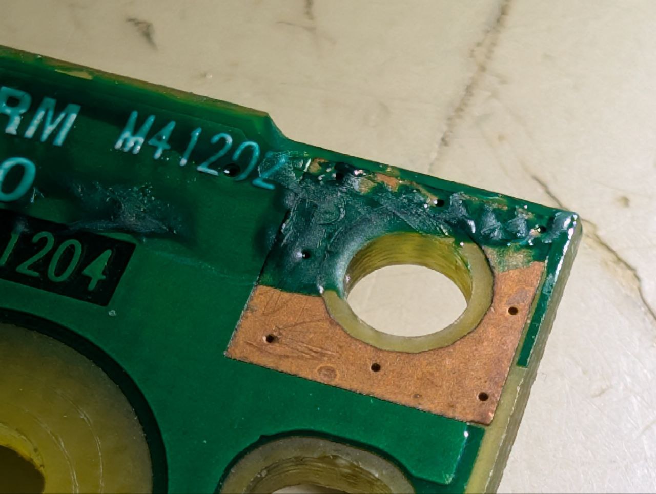
After the modification, I soldered a wire to LED+ and V- each to power the whole thing directly with \(5\,V\).
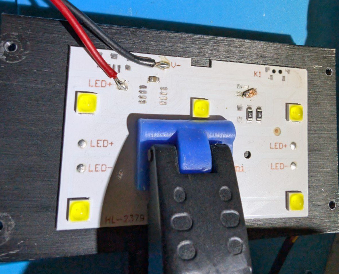
The image shows the bridged pads from the transistor. Operating the board in this state results in a power consumption of approximately \(10\,W\).
Finishing with a housing#
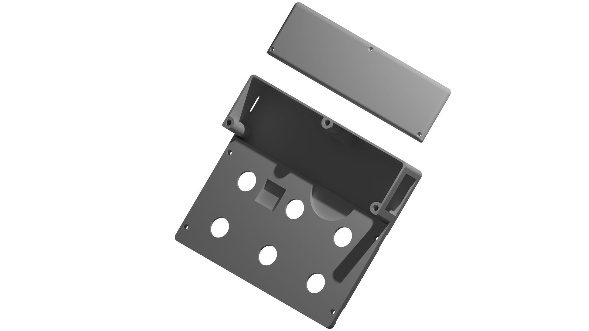
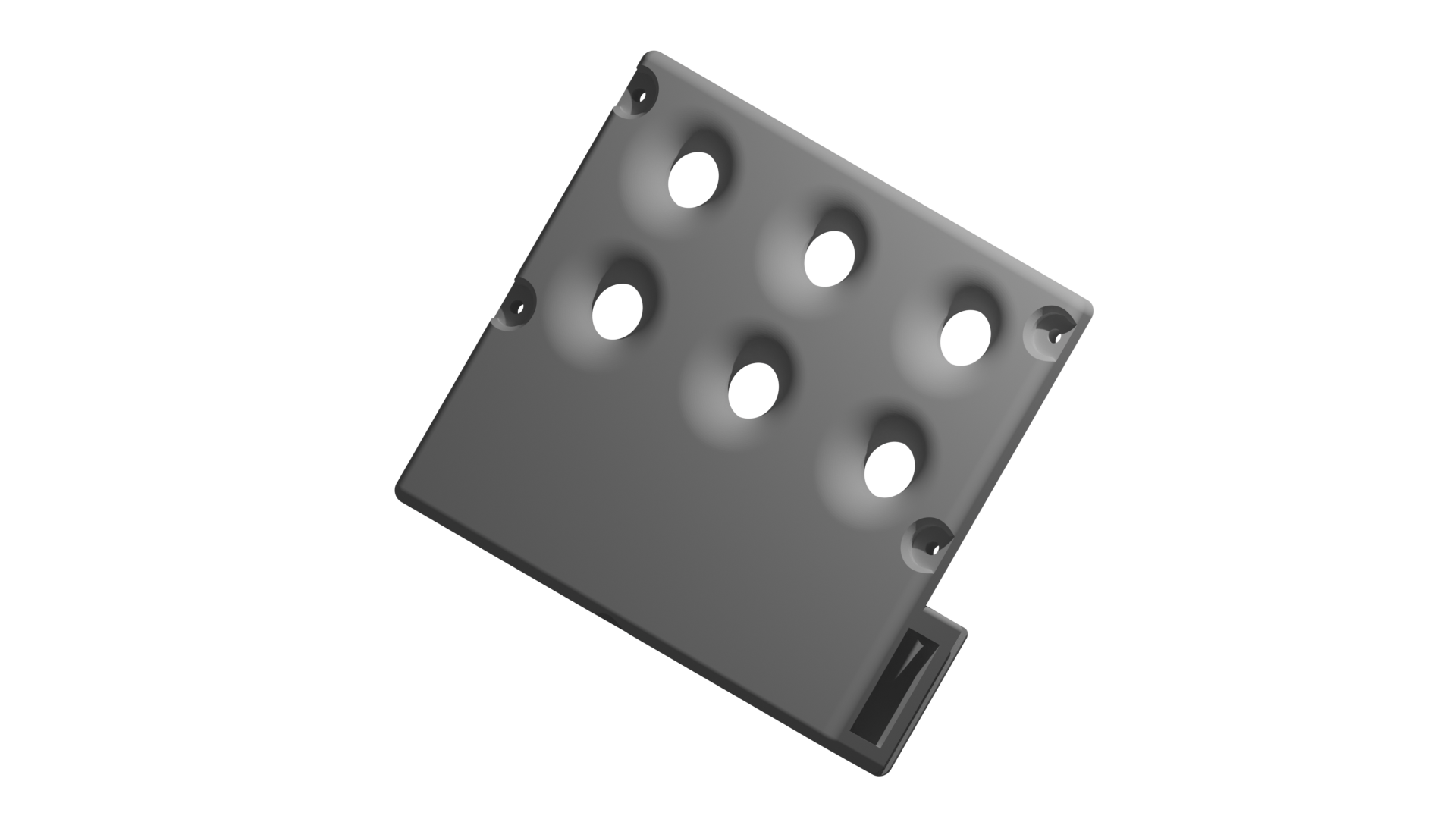
To get things together, I threw up a quick design in FreeCAD. The design should feature:
- Clamping pressure on the LED PCB to the heat sink
- Letting the light through (kinda obvious)
- Place for a switch (i found a two level switch in my arsenal)
- Place for a DC-DC buck converter
- Place for a USB C PD receptacle
- A tripod thread mount
- Should be FDM printable
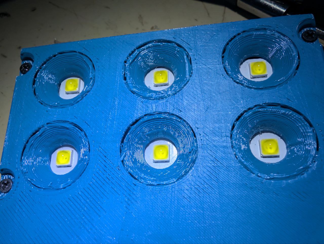
Ok The print settings were less than optimal. I have left the slicer in the draft setting as i wanted a quick result. Especially when printing the hefty chamfers around the LEDs towards the bed this was not a good idea.
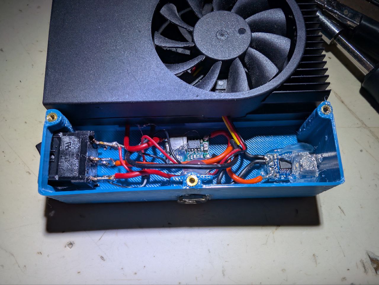
As this will be a one-off project, the electrical work inside is hand wired and fixed in place with hot glue. The input is a module with a USB C port and an IC that is requesting \(12\,V\) via USB PD. After the input, there is a two way rocker switch with a diode between the output terminals. This way, the light is on in stage I and II but the fan only operates in stage II. Up to this point the Switch is only switching the \(12\,V\) coming in via USB PD. Because that would fry the LEDs, I have put in a mini360 DC-DC Converter, set to \(5\,V\). It is the same DC-DC converter as I used in the RICOH Theta SC revival.
I have added a \(\frac{1}{4}"\) screw terminal to the bottom so i can hang the lamp over a pcb with UV curable resin with a magic arm.
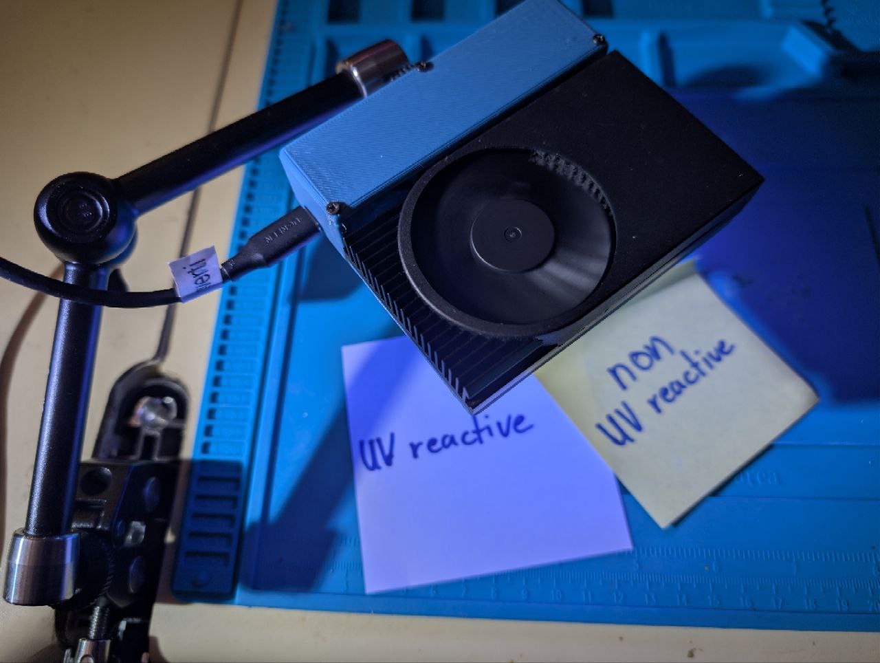
And now the only thing left is a test on the resin i was doing this whole thing for.
So the quick mod works for the few PCB repairs i need to do from time to time. If i will ever modify this thing further, i will definitely reprint the housing with more appropriate settings. Keep in mind, that the five minutes needed for curing would have required 25 presses on the power button and me being present for that every time.